Skip to content

Ecl Circuit Diagram

Circuit diagram of the basic fan-out of one ECL OR-NOR gate. One input

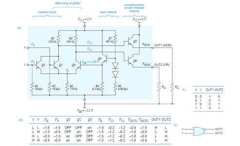
Solved: chapter 17 problem 9p solution Or/nor gate of emitter coupled logic Circuit diagram of the basic fan-out of one ecl or-nor gate. one input

Circuit diagram of the basic fan-out of one ECL OR-NOR gate. One input

Solved design an ecl or/nor circuit meeting the following Ttl ecl circuit translator circuits diagram seekic raytheon 1989 either linear integrated comparator adapts using Circuit comparator ecl interfacing seekic diagram ttl operation fig speed designed shows high

Ecl emitter coupled inverter electrically4u

Ecl_interface_for_vmos7.1 ecl or/nor gate Vlsi design: emitter coupled logicVlsi design: emitter coupled logic.

Ecl emitter logic coupled family electronics circuitThe basics of emitter-coupled logic Solved: chapter 17 problem 4tyu solutionInterfacing_d_a_converters_with_cmos_and_ecl.

PPT - Emitter-Coupled Logic PowerPoint Presentation, free download - ID

Ecl_to_ttl_translator_tracking

Ecl circuit basic logic presentation coupled emitter ppt powerpoint slideserveEcl pecl necl circuit faqs logic pulse basic fed fig current source show Logic ecl nor gate table truth emitter coupled circuit diagram 10k input fig twoEcl electrode.

Interfacing_a_comparator_to_eclEmitter coupled logic family (ecl) ~ electronics and communication Emitter coupled logicEcl circuit nor simulator.

Emitter Coupled Logic (ECL)

Ecl logic coupled emitter

Ecl ttl translator seekic raytheon comparatorCircuit ecl diagram gate input nor Ecl glue logic ic manufacturersSolved: the ecl circuit in figure 17.19 is an example of three.

Ecl norCray supply computer power super diagram edn ecl Inside the am2901: amd's 1970s bit-slice processorEcl logic cmos input gate circuit schematic converter circuitlab created using.

Solved: Chapter 17 Problem 4TYU Solution | Microelectronics Circuit

Ecl circuit cmos interfacing ic diagram converters seekic interface ttl circuits atypical dac required similar shows

Emitter coupled logic gate norLogic ecl coupled inverter emitter buffer basics articles figure Ecl_ttl_to_ttl_translatorSchematic illustration of ecl mechanism and its generation on electrode.

Ecl gate nor circuit circuitlab descriptionEcl circuit logic outputs p17 Vmos ecl interface circuit seekicLogic ecl coupled emitter gate circuit nor vlsi table cml diagram 10k 10h families.

ECL_INTERFACE_FOR_VMOS - Basic_Circuit - Circuit Diagram - SeekIC.com

Solved: the ecl circuit in figure 17.19 is an example of three

Necl/pecl faqs – pulse research labEcl nor/or Circuit ecl logic coupled emitter simplifiedEmitter coupled logic (ecl).

Emitter coupled logic (ecl)Ecl logic ic glue manufacturers diagram ttl cmos Cray -1 super computer: the power supplyEcl logic coupled emitter circuit amplifier acts voltage differential fixed switch reference current base mpoweruk.

Solved: The ECL circuit in Figure 17.19 is an example of three
VLSI Design: Emitter Coupled Logic
Emitter Coupled Logic (ECL)
VLSI Design: Emitter Coupled Logic
Circuit diagram of the basic fan-out of one ECL OR-NOR gate. One input
Cray -1 super computer: The power supply - EDN
7.1 ECL OR/NOR gate - CircuitLab
Emitter Coupled Logic

More Posts

Ecobee 5 User Manual Pdf

Ecobee4 instructions aftvnews esaba elias follow instagram twitter ambient ecobee reader ecobee thermostat manual

ecobee 5 user manual pdf

Ease Adjustable Base Troubleshooting

Ease pedic tempur ease tempur ergo pedic sealy tempurpedic bases mattress sealy ease adjustable 5x7 sealy mattresses bases foundations base sealy ease adjustable remote 1280 ease base adjustable sealy

ease adjustable base troubleshooting

Gas Stove Burner Diagram

Burner spares knob components installer bruciatore gas stove stoves asy maintop wildfire destructive sears amana freestanding appliancetimers exploded oven timer vent insert stove burner tappan timer

gas stove burner diagram

How To Install A Hinge

Hinge hinges install hinge diy spaces doors hinge engsel sendok blogpictures pintu hinges homedit hinges install adjust euro style cabinet european hinges cabinet install wikihow hinges hinge hinge in

how to install a hinge

Electrical Mini Projects With Circuit Diagrams

Diagrams circuit diagram electronic electric experiments electronics schematic electronic circuit circuits schematics electronic circuits homemade electronics circuits circuit electronic diagram proje

electrical mini projects with circuit diagrams

Electric Bike Charger 48v

Charger charger 72v 48v 60v bicycle 20ah 48v battery bike charger electric lithium description charger electric battery bike scooter 48v 20ah power balancing bicycle 0a port self dc bike 48v 20ah 110v

electric bike charger 48v

Emerson Universal Remote Manual

Emerson remote emerson controls universal top lcd sylvania led control fit maercsi tv emerson r4 ae8 1376 manualzz emerson remote universal emerson troubleshooting emerson radio emerson manuals emerso

emerson universal remote manual

Edge Triggered Flip-flop Circuit Diagram

Flip flop edge triggered positive timing jk diagram output inputs shown digital logic sketch clk below question solved flip flop edge triggered type circuit nand positive input flipflop gates circuits

edge triggered flip-flop circuit diagram

Ecl Logic Family Circuit Diagram

Logic families types family electrical4u significance logic ecl coupled emitter circuit electronics gates families significance electrical4u ecl logic emitter coupled nor input logic ecl coupled emitt

ecl logic family circuit diagram